
A diode and a thyristor can have similar external appearances, package designs, and even some datasheet parameters. Their operating principles, however, are fundamentally different. The conduction state of a power diode is primarily determined by the voltage polarity applied to it and by the surrounding circuit, whereas a conventional thyristor can block even under forward voltage until it receives an appropriate firing signal at its gate. Once turned on, a thyristor typically latches into the conducting state and therefore generally cannot be turned off by another gate signal. Understanding this difference is important when interpreting datasheets, identifying components, and preparing technical quotation requests.
Short answer: what is the most important difference?
A power diode is an uncontrolled semiconductor device with two terminals. Under the appropriate forward polarity and operating conditions, it enters the conducting state, while under reverse polarity it blocks current. A conventional thyristor, also known as an SCR, has an anode, cathode, and gate terminal. Even under forward voltage, it can remain in the blocking state until it receives an appropriate triggering signal at the gate.
A thyristor is therefore often compared to a “controllable diode.” While this is useful as an introductory explanation, it is not a complete definition. A thyristor is a latching semiconductor switch: the gate primarily initiates turn-on, while turn-off is determined by the main current and the commutation conditions of the external circuit.
How does a power diode work?
The terminals of a diode are the anode and cathode. A diode enters the conducting state when the anode is at a more positive potential than the cathode, meaning that the diode is forward-biased. Under reverse-bias conditions, when the cathode potential is higher than that of the anode, the diode blocks and prevents current from flowing.
This makes diodes suitable, among other applications, for uncontrolled rectification, providing freewheeling or reverse-current paths, and use as auxiliary semiconductors in various power electronic topologies. However, the term “diode” alone does not define the switching speed, reverse-recovery behavior, or specific application role of the device.
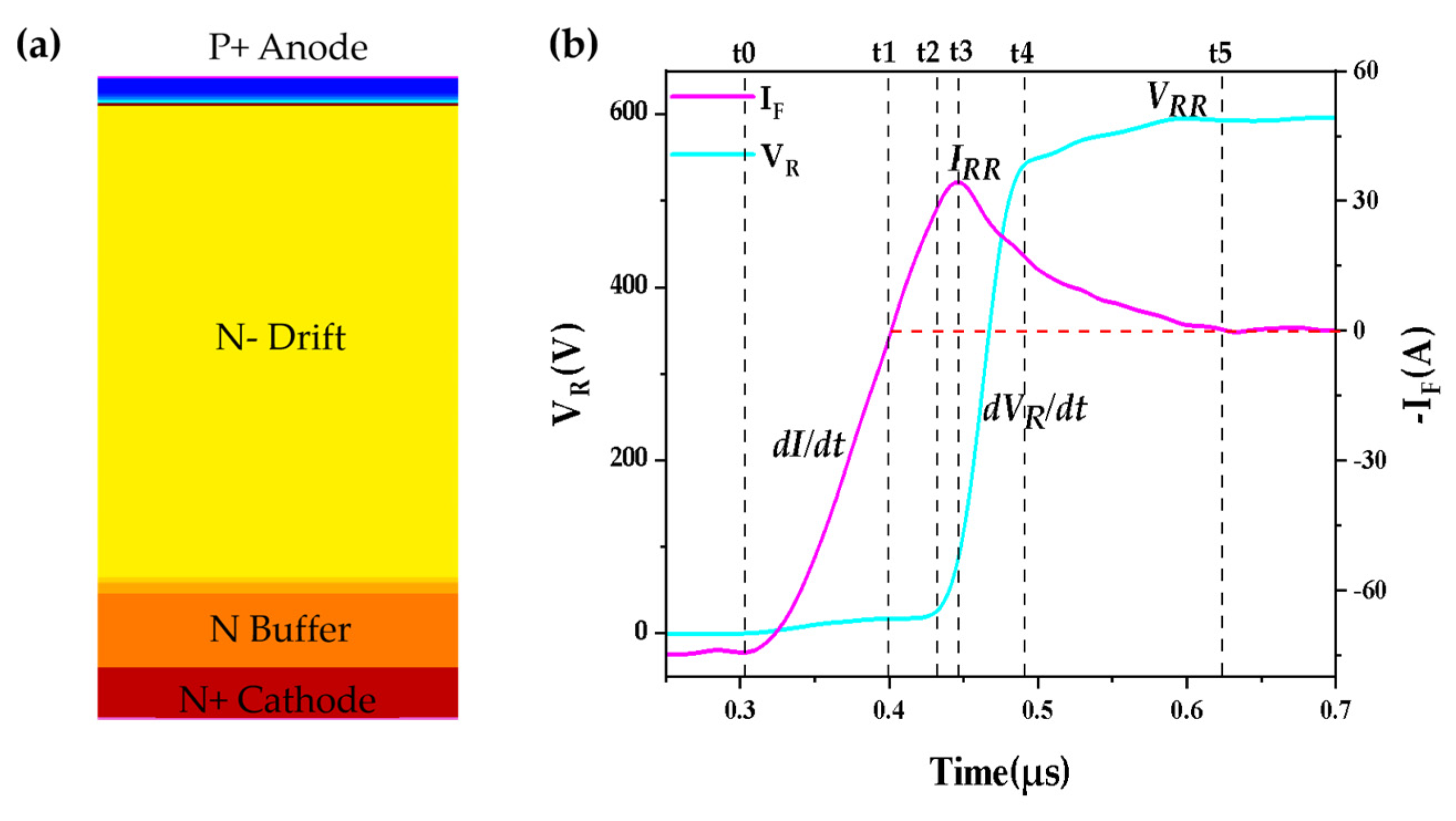
Structure of a PT-PIN fast diode and the time response of the reverse-recovery current
What makes a thyristor controllable?
The terminals of a conventional thyristor are the anode (A) and cathode (K), between which the main load current flows. The third terminal is the gate (G), through which a control pulse can be applied to initiate thyristor turn-on. When the appropriate forward bias between the anode and cathode is present, together with the main-current conditions required for turn-on, the gate current triggers the thyristor’s internal regenerative turn-on process.
Turning on a thyristor does not mean that the gate temporarily takes over direct control of the current in the main circuit. When a control pulse is applied to the gate, the thyristor becomes conductive, after which the main load current flows between the anode and cathode. During the turn-on initiation process, a gate current flows through the gate. The required gate current magnitude, control pulse duration, and other turn-on conditions must always be determined based on the parameters specified in the datasheet of the particular semiconductor device.
Latching Current and Holding Current
The latching current (IL) and holding current (IH) are two distinct thyristor parameters. Both determine the conditions under which the thyristor remains in the conducting state.
The latching current is the minimum anode current that the thyristor must reach during turn-on in order to remain in the conducting state after the gate pulse has ceased. If the anode current does not reach this value during turn-on, the thyristor may return to the blocking state after the gate signal is removed.
The holding current is the minimum anode current required for an already conducting thyristor to remain in the conducting state. If the anode current falls below the holding current, the thyristor may turn off and return to the blocking state. The holding current is generally lower than the latching current (IH < IL).
In AC circuits, thyristor turn-off typically occurs around the natural zero crossing of the main current. In DC or highly inductive circuits, however, additional commutation conditions may be required to turn the thyristor off.
Comparison of a Diode and a Thyristor
| Aspect | Power Diode | Conventional Thyristor, SCR |
|---|---|---|
| Main function | Uncontrolled, unidirectional conduction | Controlled turn-on, unidirectional conduction |
| Typical terminals | Anode and cathode | Anode, cathode, and gate |
| Turn-on | Determined by forward polarity and the circuit | An appropriate gate signal is required under forward polarity |
| Remaining on | As long as the circuit provides sufficient forward current | Once latched, the main current keeps it in the conducting state |
| Turn-off | When the conducting current ceases or the polarity changes | By reducing the main current below the holding current and providing the required recovery conditions |
| Typical applications | Rectification, freewheeling or reverse-current paths | Controlled rectification, power control, soft starters |
What does controlled rectification mean?
In a diode rectifier, the conduction timing is primarily determined by the AC supply voltage, the circuit topology, and the load. In a thyristor rectifier, the start of conduction can be delayed within the appropriate half-cycle. By varying the firing angle, the average output value on the rectified side can therefore be controlled within the range determined by the topology and operating conditions.
However, this does not mean that a thyristor can be turned on and off at any arbitrary point in time. The gate of a conventional SCR is used to initiate turn-on. Actual turn-off is closely related to the main current, the load, and the commutation conditions of the circuit.
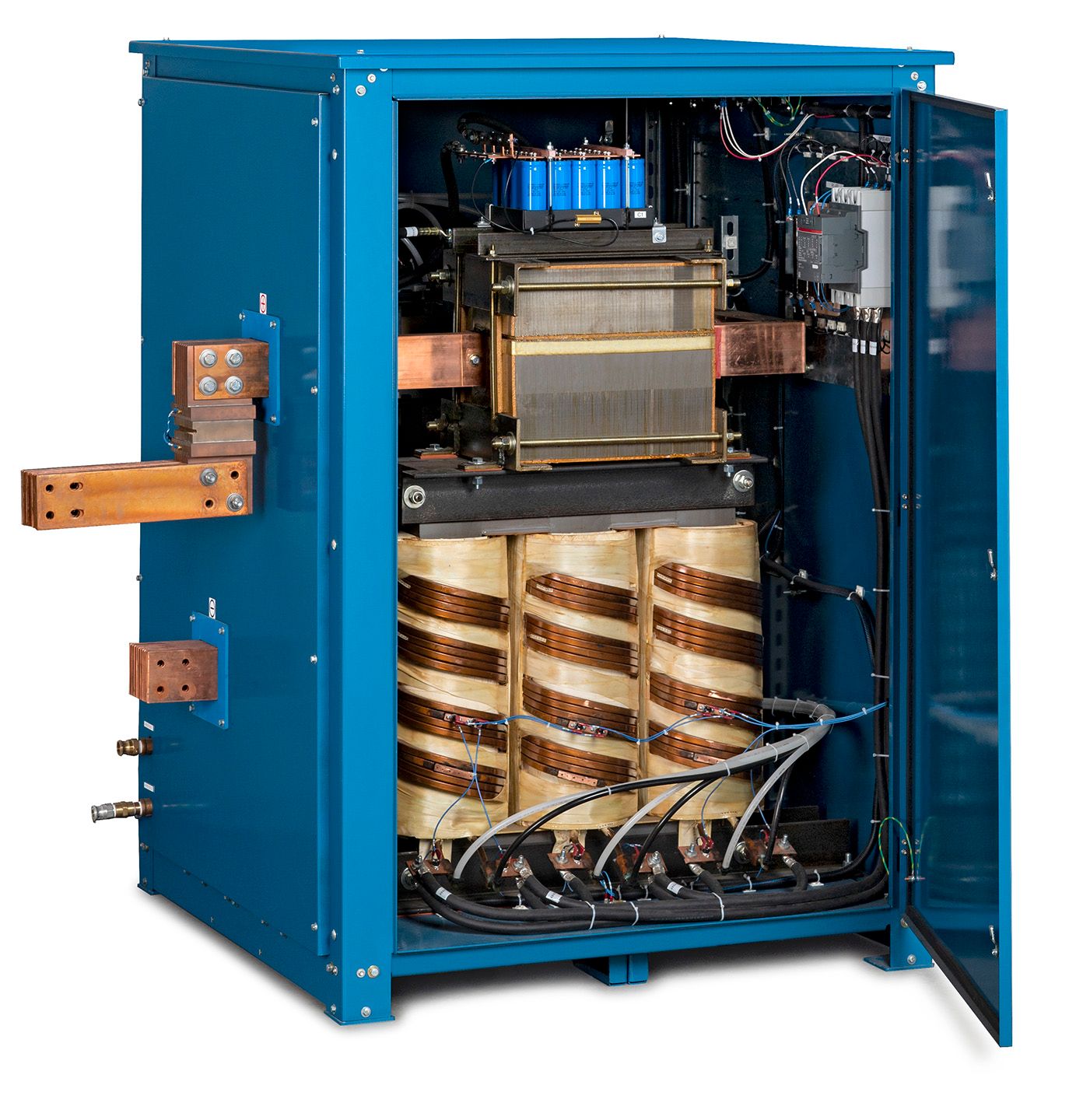
High-current industrial SCR rectifier with the enclosure open. The thyristor power stage enables controlled AC–DC power conversion in high-power industrial applications.
Where are they used?
Power diodes and thyristors are available in discrete, module, and press-pack packages. Common application areas include:
- input and mains rectifiers;
- industrial DC drives and controlled rectifiers;
- soft starters, UPS systems, and static switches;
- battery chargers, welding equipment, and high-power industrial power supplies;
- induction heating and certain high-power energy conversion systems.
The application area alone is not sufficient to select the appropriate device. Among other factors, the blocking voltage, current rating, overcurrent behavior, dynamic parameters, temperature conditions, cooling, mechanical design, and, in the case of thyristors, the gate drive must also be evaluated.
Why can’t the two devices be automatically substituted for one another?
A thyristor cannot automatically be regarded as a controlled version of a diode that can be installed in the same circuit without modification. Due to differences in the gate circuit, firing strategy, commutation, dynamic behavior, and protection requirements, the two devices can perform different system functions.
Identical voltage and current ratings and a similar package do not in themselves guarantee compatibility. For press-pack devices, mechanical dimensions, the required clamping force, and thermal transfer conditions are also important. For modules, the internal circuit configuration and terminal assignment must also be verified.
Important: Selecting the appropriate component always requires a technical assessment of the specific application and operating conditions.
Conclusion
The operation of a power diode and a conventional thyristor differs fundamentally in terms of how their conducting state is controlled. The conducting state of a diode is determined by the voltage polarity between the anode and cathode: it conducts under forward bias and blocks under reverse bias.
In the case of a thyristor, forward bias alone is not sufficient to initiate conduction. Turn-on is initiated by an appropriate control pulse applied to the gate, causing the thyristor to enter the conducting state. Once turned on, the conducting state can be maintained even after the gate signal has ceased, provided that the main current reaches and exceeds the latching current and subsequently does not fall below the holding current.
Due to their different operating principles, the two semiconductor devices are suited to different applications. Therefore, when selecting the appropriate component, it is not sufficient to consider only the part number or nominal ratings; the electrical characteristics specified in the datasheet must also be evaluated against the requirements of the specific application.
Frequently Asked Questions
Is a thyristor simply a controllable diode?
It can be described this way as a simple introduction, but the description is incomplete because of the thyristor’s latching behavior. The gate normally initiates turn-on rather than providing continuous turn-on and turn-off control.
Can a conventional thyristor be turned off using the gate?
A conventional SCR generally cannot be turned off by another gate pulse. The main current must be reduced below the holding current, and the conditions required for turn-off and return to the blocking state must be provided.
What is the difference between latching current and holding current?
Latching current is related to the minimum main current required after the turn-on process for the device to remain in the on-state. Holding current is the current level below which an already conducting device can turn off, provided that the required recovery conditions are also satisfied.
Can a diode and thyristor be distinguished by their package?
A separate gate terminal can be an indication of a thyristor, but the external construction does not always provide unambiguous identification. The part number, datasheet, and terminal assignment should also be checked.
Can a diode be replaced by a thyristor with the same voltage and current ratings?
Not automatically. Differences in control, circuit configuration, dynamic behavior, cooling, and mechanical construction mean that a technical evaluation is required.
Not sure whether the installed component is a diode or a thyristor?
Send us the exact part number, available datasheet or clear photographs showing the complete marking and terminals. For a new application, include a short description of the equipment and operating conditions. Budaker can help prepare the component identification, sourcing request or technical consultation.
- part number and known manufacturer;
- datasheet or clear photographs of the complete marking;
- short equipment and application description;
- required quantity and requested delivery date.
Források
Infineon Technologies: Power Diodes and Thyristors.
STMicroelectronics AN4607: Basics on the thyristor structure and its application.
STMicroelectronics AN302: Thyristors and TRIACs, holding current.
STMicroelectronics AN303: Thyristors and TRIACs, latching current.
Hitachi Energy: Thyristors; Diode and thyristor modules.