
A power semiconductor datasheet often lists multiple values for a given parameter. Some parameters may have minimum, typical, and maximum values, which have different meanings and cannot be used in the same way during the design process. The values provided in datasheet tables are also associated with specific test conditions, such as a particular temperature, current, voltage, or control condition.
Therefore, correctly interpreting a datasheet requires more than simply examining the specified voltage or current value. It is necessary to determine whether the given value represents a limit, a guaranteed characteristic, or a typical value, and to check the conditions under which it was determined. In this article, we explain how to correctly interpret the values, test conditions, and characteristics specified in power semiconductor datasheets.
Quick answer: always read a value together with its entire row
A value specified in a power semiconductor datasheet can only be properly interpreted when the associated parameter, unit, and test conditions are taken into account. A value such as “1200 V”, “450 A”, or “1.8 V” alone does not indicate whether it represents a limit, an operating characteristic, or a typical value specified under defined measurement conditions.
As a first step, therefore, do not simply look for the largest numbers. Instead, examine the structure of the datasheet and the purpose of the individual tables. Absolute maximum ratings, electrical characteristics, thermal characteristics, characteristic curves, and test conditions provide different types of information and must not be confused with one another.
Maximum rating: a limit, not a design target
An “absolute maximum rating” specifies a defined limit beyond which the semiconductor may be damaged or its reliability may be compromised. These values do not mean that the component should be operated continuously or repeatedly at exactly this level. The actual operating conditions of the application and the required safety margins must also be taken into account during the design process.
It is particularly important to determine whether a current rating applies to continuous operation or to a pulse of a specified duration. Datasheets often specify pulsed current capability together with the pulse duration and junction or case temperature. Such a value therefore cannot automatically be interpreted as a continuous current rating.
For voltage ratings, it is also necessary to check whether the specified value refers to a repetitive or non-repetitive voltage peak. The two ratings may represent different levels of stress and different permissible applications, so the designation and the associated conditions must always be taken into account.
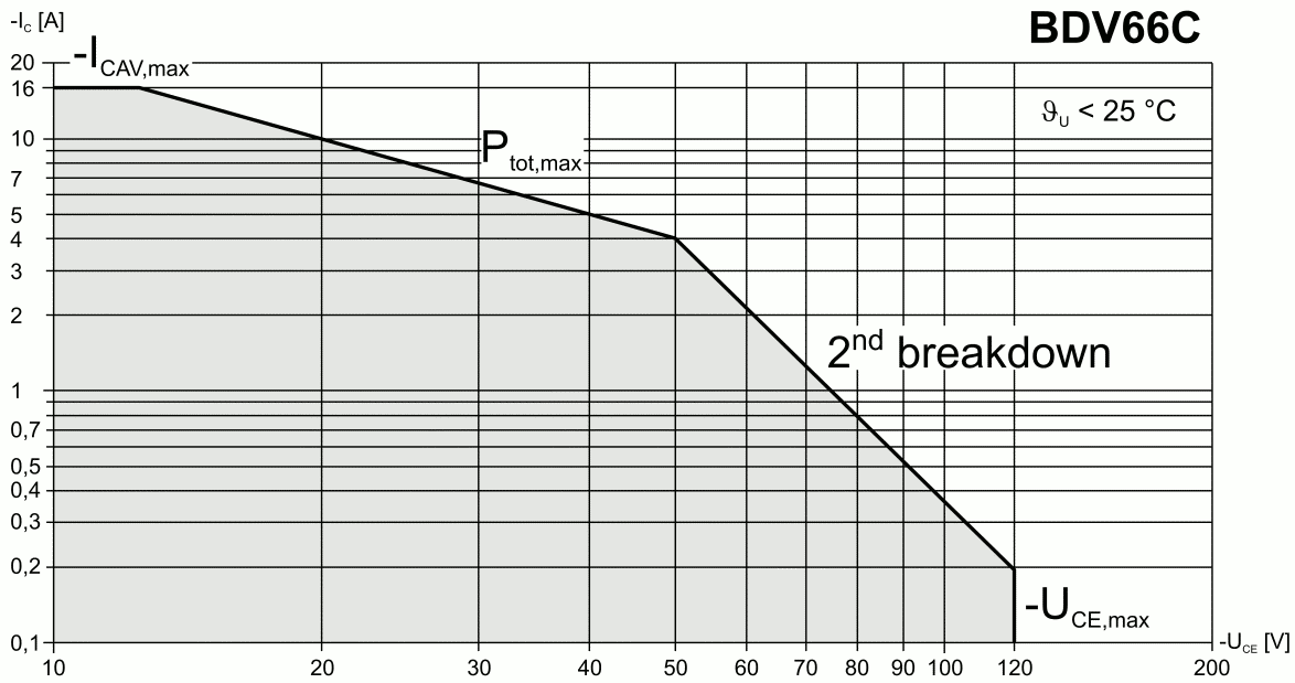
Minimum, maximum, and typical characteristics
In an electrical characteristics table, some parameters may be specified with minimum, typical, and maximum values. These values provide different types of information and therefore cannot be used interchangeably.
| Data type | What does it indicate? | How should it be used? | Main risk |
|---|---|---|---|
| Maximum rating | The upper limit specified by the manufacturer that the component must not exceed under the stated conditions | To define the limits of the application | Interpreting it as a recommended operating value |
| Guaranteed maximum | The highest value guaranteed by the manufacturer under the specified test conditions | To assess worst-case conditions and define the design range | Ignoring the test conditions |
| Guaranteed minimum | The lowest value guaranteed by the manufacturer under the specified test conditions | To verify the required minimum performance or operating condition | Replacing it with a typical value |
| Typical value | The characteristic value of the parameter under the conditions specified by the manufacturer | For comparison, estimation, and assessing expected operation | Treating it as a guaranteed value or tolerance limit |
| Characteristic curve | Shows how a parameter changes as a function of one or more other characteristics, such as current, voltage, or temperature | To examine component behavior and relationships between parameters | Interpreting it as a guaranteed limit |
A typical value provides a useful reference for assessing the expected behavior of a component, but it does not by itself represent a guaranteed limit. If the design depends on the lower or upper limit of a parameter, the guaranteed values specified in the datasheet and the manufacturer’s relevant application guidance must be taken into account.
The test condition is part of the value
Datasheet notes such as “test conditions”, “conditions”, “note”, or similar designations define the conditions under which the specified value is valid. For example, switching losses may depend on collector current, DC-link voltage, gate voltage, external gate resistance, junction temperature, and the characteristics of the test circuit.
Two data points can only be directly compared if the relevant test conditions used to determine them are identical or sufficiently comparable. The same parameter name alone does not mean that the two values were determined under the same conditions.
- Check the junction, case, or ambient temperature.
- Examine the current, voltage, and control conditions.
- Look for the pulse duration, frequency, and duty cycle if these are relevant to the measurement.
- Read the footnotes and references relating to the test circuit.
- Check whether the specified value is typical or represents a guaranteed limit.
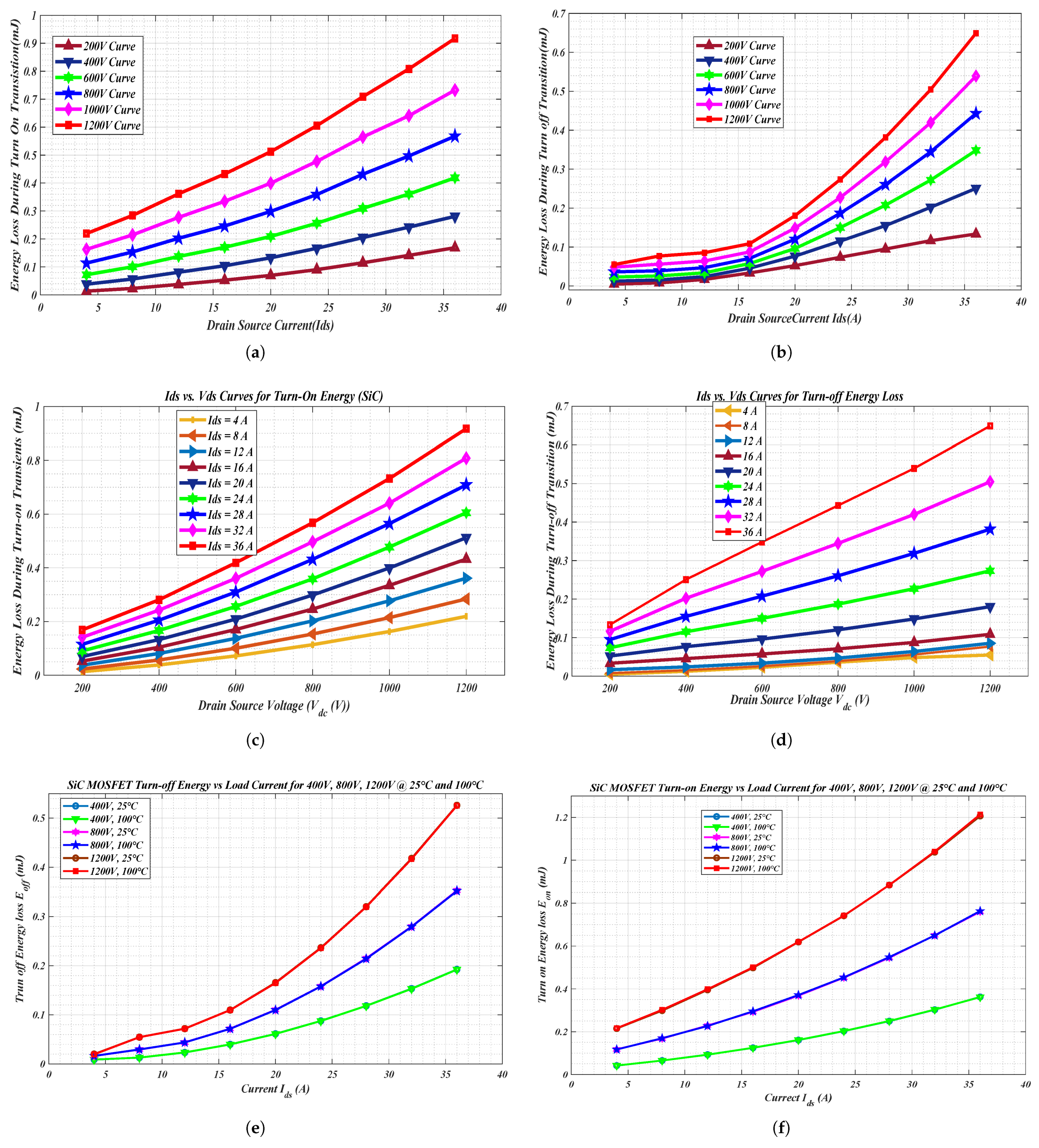
Temperature is not a secondary consideration
Many electrical and thermal characteristics of power semiconductors depend on temperature. When interpreting a datasheet, it is therefore necessary to distinguish between ambient temperature, case temperature, and semiconductor junction temperature.
If a parameter is specified at a defined case or junction temperature, the value can only be compared with other data when the relevant conditions are taken into account. The maximum junction temperature is an absolute limit and must not simply be treated as a recommended continuous operating temperature in the thermal design of an application.
When interpreting thermal resistance, it is also necessary to check between which two points it was determined. For example, a datasheet may specify junction-to-case or junction-to-ambient thermal resistance. In the case of modules, the thermal interface material, cooling surface, mounting method, and cooling system design can all affect the actual heat dissipation.
Curves show relationships, but they do not replace limits
Characteristic curves show how a given parameter changes as a function of another characteristic, such as current, voltage, or temperature. Datasheets may use such curves to illustrate, for example, changes in forward voltage, switching energy, gate charge, or transient thermal impedance.
Curves are primarily intended to help understand component behavior and the relationships between parameters. Unless the manufacturer explicitly identifies a value as guaranteed or as a limit, a value read from a curve should not be treated as a guaranteed specification.
When reading a curve, first identify the axes and their scales. Some diagrams use a linear scale, while others use a logarithmic scale. Then check the temperature, control conditions, current, voltage, or pulse duration associated with the curve. Finally, the value read from the graph should always be interpreted together with the relevant tabulated data and limits in the datasheet.
Preliminary, target, and final datasheets
Not only the individual technical data but also the document status of a datasheet can be important. The designation “target” generally refers to a development target value, a “preliminary” datasheet may contain preliminary technical information, while a “final” document may represent the final specification for a released product. The exact meaning should always be interpreted according to the documentation practices of the particular manufacturer.
Before purchasing or evaluating a replacement component, it is worth checking the datasheet version, issue date, and revision. A later datasheet version may exist for the same part number and may contain modified technical data, clarified test conditions, or additional notes.
Comparing datasheets in a safe sequence
The evaluation of a replacement component should not begin by comparing only a few key nominal ratings. First, the component type and technology, voltage and current ratings, package, and – where relevant – internal circuitry and topology should be checked. The thermal limits, static and dynamic characteristics, control requirements, insulation characteristics, and mechanical data can then be examined.
Similar voltage and current ratings, or a similar package, do not by themselves prove that two components are interchangeable. Differences may exist in the internal circuitry, gate-drive requirements, dynamic behavior, insulation system, pin configuration, mechanical design, thermal path, and short-circuit capability.
Important: Selecting a suitable component always requires a technical evaluation of the electrical, thermal, and mechanical conditions of the specific application.
Conclusion
Correctly interpreting a power semiconductor datasheet involves more than simply locating a single voltage or current value. Every value must be interpreted together with the parameter designation, the type of value, and the associated test conditions. It is particularly important to distinguish between absolute maximum ratings, guaranteed minimum and maximum values, and typical values.
Characteristic curves help explain component behavior and the relationships between individual parameters, but they do not necessarily represent guaranteed limits on their own. When technically comparing two components, it is therefore not sufficient to compare only their nominal voltage, current, or package. The test conditions, electrical and thermal characteristics, and application requirements must also be taken into account. Ultimately, selecting the appropriate component always requires a technical evaluation of the operating conditions of the specific application.
Frequently Asked Questions
Is a typical value a guaranteed specification?
Generally, no. A typical value indicates the characteristic value of a parameter under the test conditions specified by the manufacturer. If the lower or upper limit of a parameter is critical to the design, the guaranteed values specified in the datasheet and the manufacturer’s requirements for that parameter must be taken into account.
Can the component be operated continuously at its maximum rating?
A maximum rating is a limit and is not automatically a recommended continuous operating value. The actual permissible load must be determined based on the operating temperature, heat dissipation, load profile over time, transient stresses, and other application conditions.
Why can the value of the same parameter differ between two datasheets?
The difference may be caused, for example, by the test temperature, the applied current or voltage level, the control conditions, the pulse duration, the test circuit, or the classification of the specified data. The two values can therefore only be properly assessed after comparing their associated test conditions.
Can a value read from a characteristic curve be considered guaranteed?
Not necessarily. Characteristic curves generally illustrate the typical behavior of a component under specified conditions. A value read from a curve should only be treated as a guaranteed specification if the manufacturer explicitly defines it as such in the datasheet.
Are voltage, current, and package sufficient to select a replacement component?
No. Assessing interchangeability requires checking, among other things, the component type and topology, control requirements, static and dynamic parameters, thermal characteristics, insulation properties, pin configuration, and mechanical design.
Have a question? Contact our team!
Choosing the right power semiconductor requires considering not only the datasheet specifications, but also the real-world operating conditions of the application. If you need assistance with a specific component or technical requirement, our team is ready to help.
Sources
Infineon Technologies: Industrial IGBT Modules – Explanation of Technical Information, AN 2011-05, V1.2.
Infineon Technologies: Datasheet Explanation Update for Automotive MOSFETs.
Hitachi Energy: 5SDD57X6500 Rectifier Diode datasheet, maximum rated values, characteristic values and test conditions.
Hitachi Energy: Semiconductors official product and technology page.